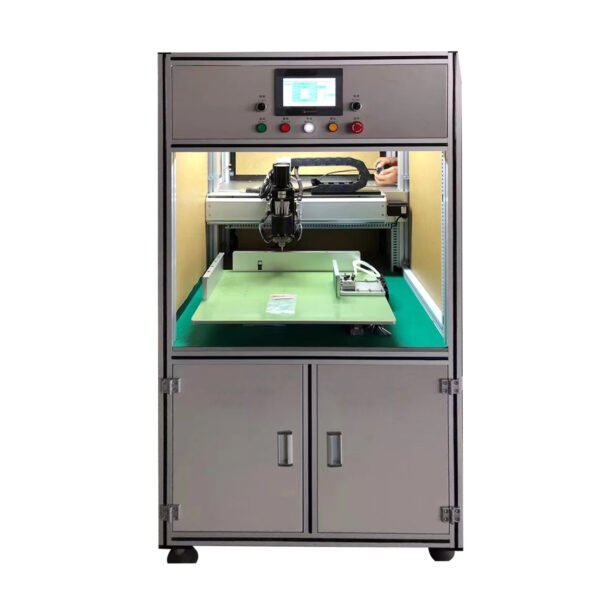
1 Electrical characteristic
High performance industrial grade 32-bit ARM+DSP+FPGA
32 MB user storage space
800×600 TFT LCD brightness adaptive, LED backlit LCD display
Four-wire resistive touch screen
RS232 communication interface
USB interface
Full height anti-interference switching power supply
200W/100W servo motor drive
2 Technical index
Pulse equivalent: 0.001mm
Processing speed: 0.01-15000mm/min
Programming coordinate system definition: in line with ISO-841 international standard
Mean time to failure (MTBF) : more than 10,000 hours
The maximum processing range of Y-axis is 500mm. (600MM need to be customized in advance)
Z-axis maximum processing range 400mm
Relocation accuracy ≤0.1mm
The maximum weight of the workbench is 20kg
Maximum height of workpiece 80mm
The height of the electrode clamp to the workpiece is adjustable from 5-20mm
Z-axis stroke of welding head 30mm can be set
The maximum compression retraction of the pin holder is 8mm
3 Equipment use environment:
Dimensions: 1000 (L) X800 (W) X1620 (H) X700 (table height)
Equipment weight: 130kg
Indoor movement: Bring your own caster to push
Power consumption: ≤500W (excluding the capacity of the welder)
Power supply voltage: 220V (+ 10%, -15%), frequency 50Hz± 1%
Power plug; National standard 10A flat three-pin plug
Power capacity requirements; (Depending on the welder, consult the manufacturer when installing)
Fuselage air source according to port type; 8mmD Gas pipe inserted directly
Air source pressure; > 5kgf/cm2
Air source consumption; 0.35 m3 / h
Operating temperature 5 ~ 40℃, relative humidity 40-80%
Storage and transportation temperature 0 ~ 55℃, relative humidity less than 90% (40℃)
Packaging and transportation: PE film and PE guard log pallet plus wood protection frame (when not required)
4 Welder connection
With a welding machine
Can be used with a variety of welding machines
Welding machine start signal
The welding trigger wire is connected to the foot trigger port of the welding machine
Welding machine energy switching
The energy switching wire is connected to the external corresponding functional interface of the welder. (Optional depending on welding power supply)
Welding trigger signal
Access the system, unified deployment.
Welding machine voltage detection
The voltage detection wire of the welding machine is connected to the welding head, and the special detection wire on both sides of the welding pin clamp is connected to the wiring position (depending on the welding power supply).
6 Welding machine debugging
Welding machine parameter
The parameter debugging of the welding machine is mainly based on different welding machines and use conditions
Action between welder and equipment
At the beginning of the commissioning of the equipment, it is necessary to give the welder sufficient welding time in the processing program, so that the welder can complete the welding action, and then appropriately reduce the time to the welder after the normal welding to improve the efficiency of the equipment.
Welding fixture
Welding different products should be matched with different fixture designs Needle length adjustment
The length of the welding needle should not be too long under appropriate circumstances to reduce energy loss. Adjust the length of welding needle with accessories to adapt to different product welding
Head stroke adjustment
The equipment is compatible with 65MM and 70MM height cell spot welding so that the head stroke can be adjusted. The welding head stroke has a default maximum stroke when welding the 65MM height of the cell. When welding the 70MM height of the cell, adjust the height of the welding head and adjust the depth in the “4-axis machine parameters”.
7 maintenance
Routine maintenance
Clean and wipe the welding spatter on the movable table surface and platform, welding head and plate with dry cloth for each work shift.
Clean the welding needle in time during work
Replace badly worn pins in time
Turn off the power when you leave work.
Check the amount of water in the cooling tank in time.
Weekly maintenance
Focus on cleaning and erasing the surface of the table and the platform and welding head and face plate welding spatter.
Check the amount of water in the cooling tank inside the machine.
Quarterly maintenance
Open cover plate and give # 0 butter on all moving parts (no more)
Half-year maintenance
Open the machine door and butter the following parts:
Guide gauge moving parts
Screw moving parts
Welding head guide shaft assembly


